RS4 Exhaust Flap Control
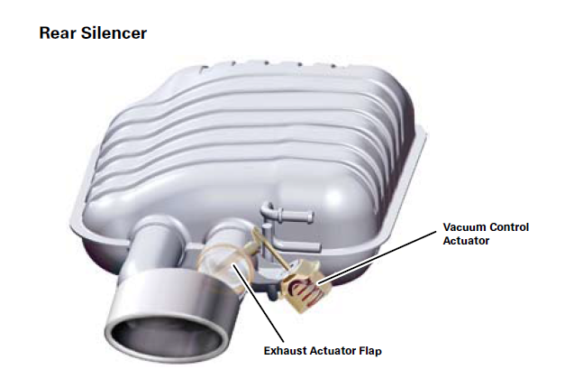
March 29, 2015 – 9:50 pm

The B7 RS4 comes with a neat feature, there are vacuum-controlled flaps in the exhaust that keep it quiet around town but can be opened when you’re enjoying the car on a back road for a little more power and to hear the V8 sing. They’re also open when the car first starts up, which is why it makes such a nice noise when you start it up!

Exhaust Flaps

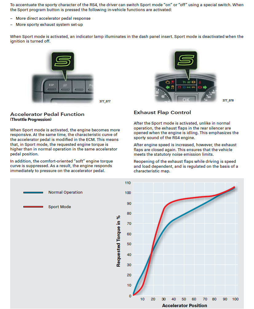
The only problem with this system is that to open the exhaust flaps you have to put the car in “S” mode, which also means that the accelerator curve is changed to be much more abrupt (or “direct”, as Audi would describe it). I don’t particularly enjoy the non-linear throttle response in S mode, and found the car much more controllable during autox events with it disabled. The other problem with this arrangement is that even in S mode, “After engine speed is increased, however, the exhaust flaps are closed again. This ensures that the vehicle meets the statutory noise emission limits.”.

Sport Button

That’s no fun, but as it happens there is a solution! The exhaust flaps are controlled by a vacuum solenoid behind the left rear wheel well, which controls whether vacuum from the engine is allowed to pull the flaps closed. The solenoid gets 12v from a connection shared with the leak detection pump, and when in “normal mode” the other pin is grounded via an ECU pin. This “opens” the solenoid and allows vacuum to close the flaps. (As an aside, this is why the flaps are open at startup, the solenoid vents when it doesn’t get 12v so the flaps stay open until there is enough vacuum from the running engine to pull them closed.)

So, armed with this knowledge we now know that we can add a switch to the connection between the ECU and the solenoid and control whether the flaps are open or closed! The rest of this post details how to install the switch and a 1k ohm resistor which will prevent the ECM from throwing a fault code when we disconnect the solenoid.

You will need:

  • 1x toggle switch
  • 1x 1k ohm 1/2 watt resistor
  • 2x crimp connectors
  • 1x wire tap

There are 2 wires we need to locate to complete the mod. The first is grey with a black stripe, and goes through pin 10 on the T17j brown connector in the connection block just underneath ECM 1 (the RS4 needed 2 ECMs to handle all the functions required), which is under the windshield cowling. The grey/black wire is the control signal from the ECM to the exhaust flap solenoid.

The second wire is green with a yellow stripe, and goes through pin 1 on the T17d red connector in the same connection block. This wire supplies 12v to the solenoid, and we will tap into it to fool the ECM into thinking the solenoid is always connected.

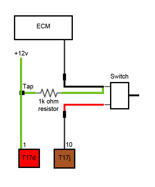
Here is a diagram of what we’re putting together, the switch cuts power to the solenoid to open the exhaust flaps while the 1k ohm resistor creates a circuit from the 12v source to the ECM pin to avoid creating an open circuit fault when the solenoid is disconnected.

Connection Diagram

Let’s get started!

Start by disconnecting the battery!

To remove the windshield cowling you’ll first need to remove the windshield wipers by popping the rubber caps at the base of the wiper arms, undoing the nuts and wiggling the arms off. Once the arms are off, remove the cowl trim by lifting it up and pulling gently toward you.

Next, remove the 3 small black metal clips that hold the windshield cowl trim in place and pull it free from where it clips along the bottom of the windshield. This will give you access to remove the T30 torx screws that hold down the ECM cover, and with that removed you’ll be left with something like this:

ECM Cover Removed

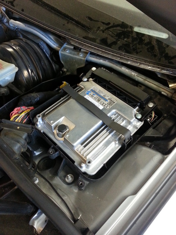
Use a flat screwdriver to pop the hold-down clip on the ECM, and pivot it out of the way to get access to the connector station underneath. At this point you’ll most likely want to remove the driver’s side lower dash panel (One 8mm bolt behind the fuse panel cover and 2 more at the bottom of the dash panel), so you can get access to the dash to fish wire through and to mount your switch.

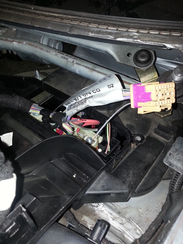
Unplug the brown connector and locate the grey/black wire that goes to pin 10, this is the wire we need to cut. Here you can see it after I made the cut, I fished the cut end of the wire back through the harness label after I cut it to have more wire to work with in the next step.

Cutting the solenoid control wire

I used male/female crimp-on spade connectors to make the connections, so that the mod is easily reversible if desired. At this point connect each of the cut ends to a separate piece of wire (I used some 18 gauge red/black “zip wire”) so you can fish it back down into the dash. Note which side goes to the ECU, since this is the wire we’ll connect the resistor to in the next step.

Connectors crimped on

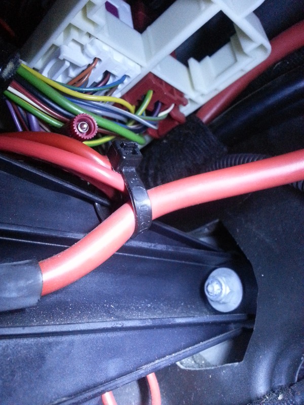
Locate the green/yellow wire on pin 1 of the red connector, then use a wire tap (I used a Posi-Tap) to tap into it and connect a wire to one leg of the 1k ohm resistor. I tapped into this wire from inside the car, but you can also tap in where it comes out of the top of the connector.

Wire tap

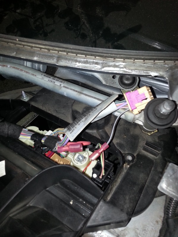
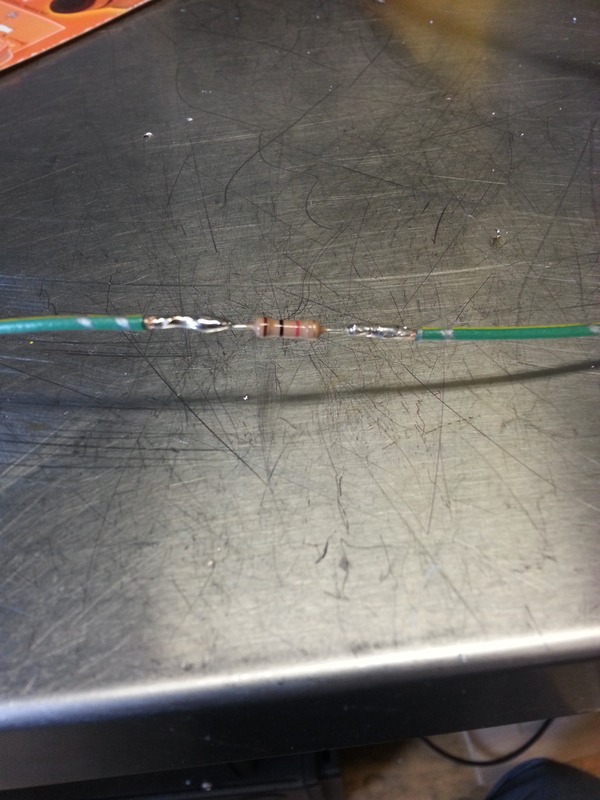
Here you can see the resistor soldered into a piece of matching green/yellow wire I happened to have. After soldering I covered the resistor with heat-shrink tubing.

Resistor

Now, take the extension of the “upstream” grey/black wire coming from the ECU and the wire from the other leg of the resistor, and connect them both to 1 terminal on the switch. The extension of the “downstream” grey/black wire that goes to the solenoid should be connected to the 2nd terminal on the switch.

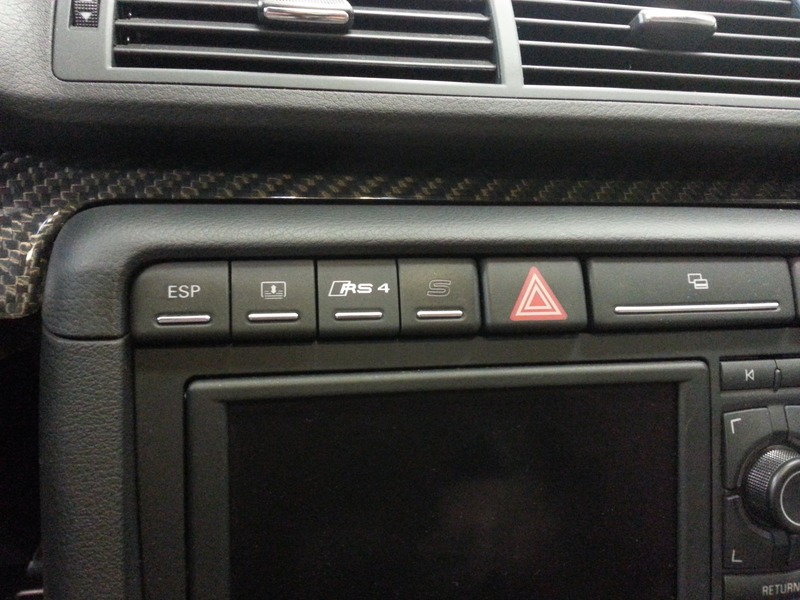
When the switch is On the exhaust flaps will work exactly as they did from the factory, when it is Off the connection to the solenoid is interrupted and the exhaust flaps will be open all the time. I wired mine to an “RS4” switch I picked up that fits into a factory location in the dash, but any switch will do. The solenoid only draws about 500ma when it’s operating, so a relay isn’t necessary as long as your switch can handle at least that current.

RS4 OEM-style switch

Put everything back together and enjoy!

Simple Storage Cabinets

February 3, 2013 – 4:14 pm

Here’s my method for making large storage cabinets without breaking the bank.

Finished Cabinets

Each cabinet is 40″ wide by 81″ tall by 14 3/4″ deep, and uses the following materials:

2 x 3/4″ 4’x8′ Maple Plywood ($39.97ea)
1.5 x 1×3 8′ Pine ($7.87ea)
66 x 1 1/4″ Kreg Pocket Hole Screws ($4.08/100)
8 x euro-style full overlay hinges ($1.00ea)
32 x #8 5/8″ spax screws ($1.94/50)
2 x brushed chrome 4″ handles ($2.52ea)
6 x 2 7/8″ Headlok screws ($18.97/50)
10 x #7 1 1/4″ spax screws ($1.94/50 to join additional cabinets)

For 3 cabinets the total was $355 + tax, or a bit more than the cost of 1 pre-built cabinet.

I chose the dimensions to get the largest cabinet from 2 4’x8′ sheets of plywood, which are cut like this:

Plans 40x14x82

First, make sure the sheets are square. The maple sheets I was using were all pretty good, but you might need to shave a little off to get them square.

Next, cut 14″ off the end of both sheets. I chose to cut on the 14″ side of the line, so my shelves and sides are 14″ minus the width of the saw blade. It doesn’t matter which way you cut, as long as it’s the same every time!

2013-01-27 11.09.14.jpg

Put the 14″ x 4′ pieces aside, then rip 2 14″ pieces off the long edge of both sheets of plywood. You’ll end up with 4 14″x82″ pieces and 2 20″x82″ for the doors.

DSC05381.JPG DSC05382.JPG

Set 2 of the 14″x82″ pieces aside for the sides of the cabinet.

The remaining 4 14″ wide pieces are cut into 38.5″ lengths for the 6 shelves.

DSC05383.JPG

Next cut 3 38.5″ lengths of 2×3, these will be the cleats that hold the cabinet to the wall.

Now that all the pieces are cut, drill 4 pocket holes in each end of the shelves, and 6 pocket holes in each cleat.

DSC05385.JPG DSC05384.JPG DSC05386.JPG 2013-01-27 11.09.34.jpg

Take the cabinet sides and 2 shelves, clamp and screw together to form a box.

DSC05388.JPG DSC05389.JPG

The remaining 4 shelves can now be screwed in place. I put them at 14″, 30″, 46″ and 63″ measured from the top of the cabinet to the top of the shelf.

DSC05390.JPG

The cleats are screwed in place from the back, and the cabinet itself is done.

DSC05391.JPG 2013-01-27 11.08.58.jpg

The cabinets are mounted to the wall by screwing through the drywall and into the studs. Start by marking the wall where the left edge of the cabinet will be, then locate the studs and measure the distance to pre-drill clearance holes in each cleat.

Now the cabinet can be set against the wall at the desired height, leveled up and screwed in place.

When mounting multiple cabinets, each subsequent cabinet is screwed to the previous one with 1 1/4″ screws to keep everything tight.

DSC05392.JPG DSC05393.JPG DSC05394.JPG

Now for the doors…

Start by measuring the final assembled width of the cabinet, divide by 2 and then subtract 1/16″ for clearance to find the width of the doors. Trim or plane the door panels to their final width, and install 4 hinges on each door.

I used a shop-made jig to route the hinge pockets, but you can also use a forstner bit. Cut the pockets and mount the hinges, then attach the doors to the cabinets.

2013-02-02 16.33.32.jpg 2013-02-02 16.33.42.jpg 2013-02-02 16.33.50.jpg 2013-02-02 16.34.00.jpg

Adjust the doors as you go so they’re level and have an even gap between each one, then attach the handles and admire your handiwork!

2013-02-02 17.21.48.jpg 2013-02-02 18.18.59.jpg 2013-02-02 18.51.25.jpg

You can use the same method to make cabinets that are 37.5″ wide, 15″ 3/4″ deep and 81″ tall, with the same materials list:

Cabinet Plans 37.5x15x81

Here is a set of shelves without doors made from a single piece of plywood using the same technique, total build cost was under $60.

DSC05377.JPG Shelf Plans 36x12x72

I’m very pleased with how they turned out, and was surprised how easily they went together. This was my first project using the Kreg system, and as long as the joints are properly clamped they go together very well.

I made the shelves using aluminum angle as a saw guide, but it was a pain to get everything lined up and very easy for the saw to wander off line away from the guide. The EZ-Track system made things easier to lay out and in general performed very well, though you have to be careful to keep the saw level at the end of the cut when the outside “foot” on the base runs past the end of the workpiece.

Winter in Central NY

January 9, 2010 – 7:11 pm

We just got a new video camera, so I thought I’d make a little video to show everyone back home what winter is like in our neck of the woods.

DomTuned

October 6, 2009 – 7:58 pm

Wow, it’s been forever since the last update, and a lot has happened in the interim. When we left off, the engine was in pieces and all the rod bearings had failed. Things were looking pretty bleak, and the car had only done 150 miles since the swap.
Read the rest of this entry »

The Teardown

May 9, 2009 – 1:10 pm

Today was D-day for splitting the block and taking a look at what was causing all that racket. I pulled the oil cooler & pan off the block first, and could see some flakes in the bottom of the pan, so I knew it was definitely a bearing.

After pulling the various plugs off the block I hefted it onto the bench and removed the flywheel, then split the case and this is what greeted me:

Needless to say, I’d found the problem.

DSCF2816.JPG DSCF2820.JPG DSCF2821.JPG

Next stop will be the machine shop to find out what will need to be done to get the crank into shape again, and have the block hot-tanked.

More pics are here.

The Joys of Rod Knock

April 28, 2009 – 6:49 am

The legacy is spread all over my garage again.

We noticed that the car was running lean under boost, and although I didn’t get any misfire codes or hear any detonation, I suspect that a rod bearing is on the way out. After replacing the fuel pump we fired the car up again and noticed a tapping/knocking sound emanating from the engine between 2000 and 2500 rpm.

So it’s time for a complete teardown, hopefully it’s just a bearing and no other damage has been done. Right now I have the engine out and on the stand, and I’m waiting for a hardened 10mm allen socket to break the notoriously-difficult cam gear bolts loose.